This tutorial will guide you through the use of the I/O Extension in slave mode and will in detail demonstrate and explain the steps required to use the powerful features available.
The following steps are required to set up and use the I/O Extension:
| 1. | Creating the application and the job. |
| 2. | Adding the net to the I/O Extension. |
| 3. | Configuring the job and effectively binding variables to physical I/O . |
| 4. | Testing the application in the RTCU Emulator. |
| 5. | Transferring the application to a physical RTCU device. |
| 6. | Monitoring the I/O by using the I/O Monitor dialog. |
1. Creating the Application and the Job
To illustrate the I/O Extension for a slave, the following small VPL program will be used:
INCLUDE rtcu.inc
VAR_OUTPUT
LED : BOOL;
END_VAR;
PROGRAM main;
VAR
cur : ARRAY [1..4096] OF DINT;
old : ARRAY [1..4096] OF DINT;
i : INT := 10000;
END_VAR;
BEGIN
IF (i > 4096) THEN
memioReadX(index:=1, mem:=ADDR(cur), len:=4096);
i := 1;
ELSE
IF NOT ( cur[i] = old[i] ) THEN
LED := NOT LED;
old[i] := cur[i];
END_IF;
i := i + 1;
END_IF;
END;
END_PROGRAM;
The above application is very simple with a single BOOL variable in the VAR_OUTPUT section and access to the memory I/O.
The logic is equally simple as the only operation is to check whether the memory has changed and toggle an output.
Despite the simplicity of the above application, it will allow us to demonstrate how to set up and configure the I/O variables so that:
•LED will be allocated to the on-board user LED.
•Memory I/O can be accessed by a MODBUS master.
For detailed information on how to create and compile the application and create the job, please refer to the Tutorial section.
2. Adding the Net to the I/O Extension
After the application and the job have been created, a net must be added to the I/O Extension.
To allow adding a net, first enable X32 or NX32 in Project Settings.
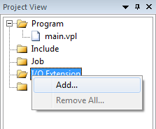
Then define a net by right-clicking on the item "I/O Extension" and then click on "Add..."
In the "I/O Extension net" it is possible to choose whether the connected RTCU device will act as a slave to let another device use its input/outputs or as a master to control the I/O devices. In this tutorial we will configure the device to be a slave in order to show the purpose of I/O expansion.
Please note that only serial channels with RS-485 capability are supported by the I/O extension. It is not possible to change the net label and the net ID as it is currently limited to defining only one net.
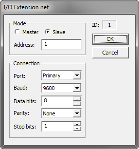
Please make sure that the "Connection" parameters (Port, Baud, Databits, etc. - see Project Control - I/O Extension net) match the parameters of the physical MODBUS network deployed and that an unused MODBUS address is used.
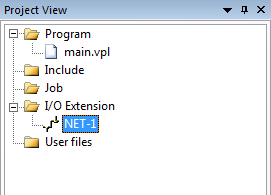
Click on "OK and a net will be created on the project tree.
4. Configure the Job, effectively binding variables to physical I/O
When working as a MODBUS slave, it is vital to remember that any I/O which will be controlled by a master must not be mapped in the job variable configuration. The reason for this is that any value written by the master will be overwritten with the application values at BEGIN-END/UPDATEIO.
Any I/O not controlled by the MODBUS master can be mapped and used. For further details, please see the Configure Job section.
The job configuration:
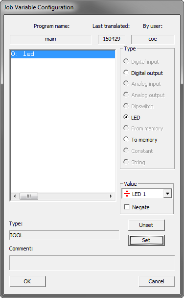
As it can be seen from the above configuration, the configuration as described in step 1 has now been defined:
•LED will be allocated to the on-board user-controlled LED 1.
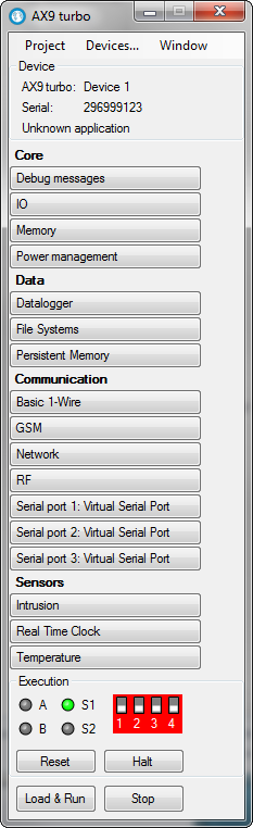
5. Test the application in the RTCU Emulator
Let us test the project that we have created above.
First refresh the job by selecting "Build" from the "Project" menu.
Then click on the "Emulator" menu item and finally click on "Emulator..." in the drop-down menu:
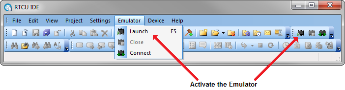
The Emulator window will appear as in the following:
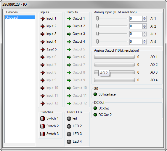
Enable the I/O window by clicking on "IO". This will bring up the following dialog:
After this enable "Memory". This will bring up the following dialog:
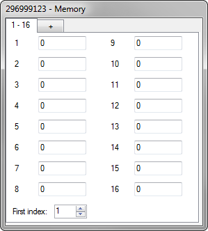
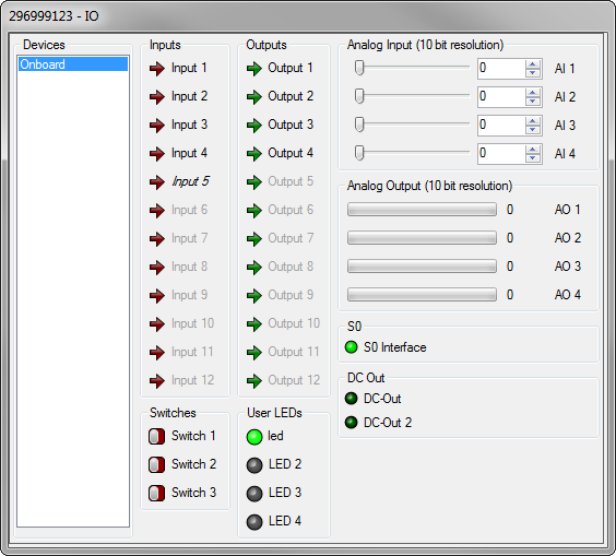
Let us start the emulator by clicking on "Load & Run" on the emulator control window. The program of the application is now running. As there has not yet been applied any values to the memory, LED will show as off. Enter a value in entry "1" of the "Memory" to simulate a master writing to holding register 4096 (see MODBUS commands for details) and wait for the LED to turn on. The "IO" window should now look like this:
6. Transfer the application to a physical RTCU device
Transferring the application to a physical device is described in the Transfer to RTCU section. As the configured I/O Extension information is an integral part of the project, it will automatically be transferred to the device. If the device attached does not support the I/O Extension information, it will simply be ignored, and the application may not operate as intended.
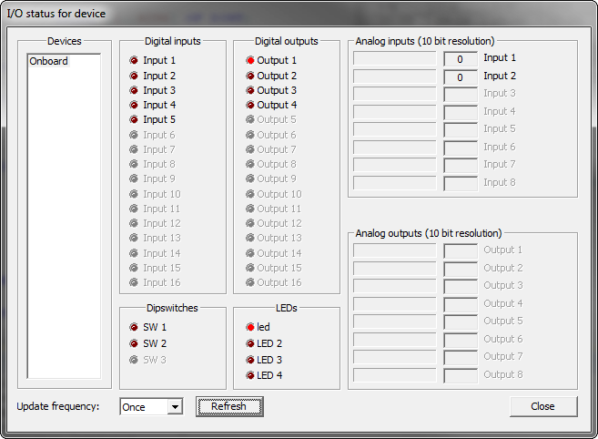
7. Monitor I/O using the I/O Monitor dialog
The Device I/O Monitor fully supports the onboard I/O and changes from the MODBUS master can easily be monitored. The following figure shows the I/O status of the project in this tutorial running on a physical device after an onboard digital input and a register value have been changed.
This is the end of the tutorial. For further information on I/O Extension dialogs, please consult the sections Project Control - I/O extension, Project Control - I/O extension net, Project Control - I/O extension device, and Project Control - Setup Module.